
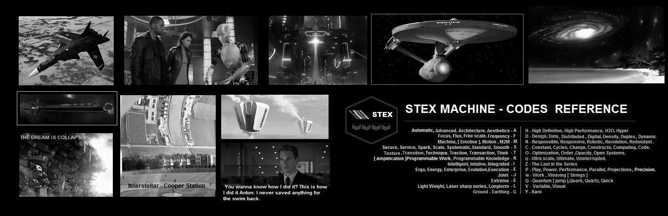
Design Bureau Technology Paradigms & Industry Projects - Twenty+ Innovative Technology Projects

|
Target Audience : SIEMENS, MITSUBISHI, ABB, MICROSOFT, IBM , ATOS, MAN AG, SCHNEIDER ELECTRIC,SCANIA, GOOGLE, APPLE, YAHOO, ACCENTURE, Intellectual Ventures, Others Enterprise Majors, Other Small Tech Pioneers, Stanford, MIT, Harvard, UCLA..... We are Confident ! |
#1 Spatial Information Projections/Information Broadcast - Technology for the STEX Grid project
Stex Advanced Design bureau has Invented this special new Information/Data Architecture or Paradigm for specialized network applications, search Applications as well as Artificial applications. Information collected on the Internet, Web Portals, search engines or social networks is called Traditional uni dimensional Data and Lacks many Technological Features such as
- Multi Dimensional Meta Data associations
- Sense of Space/Geography
- Sense of Time
- 3Dimensional spatial structure
- Domain Knowledge
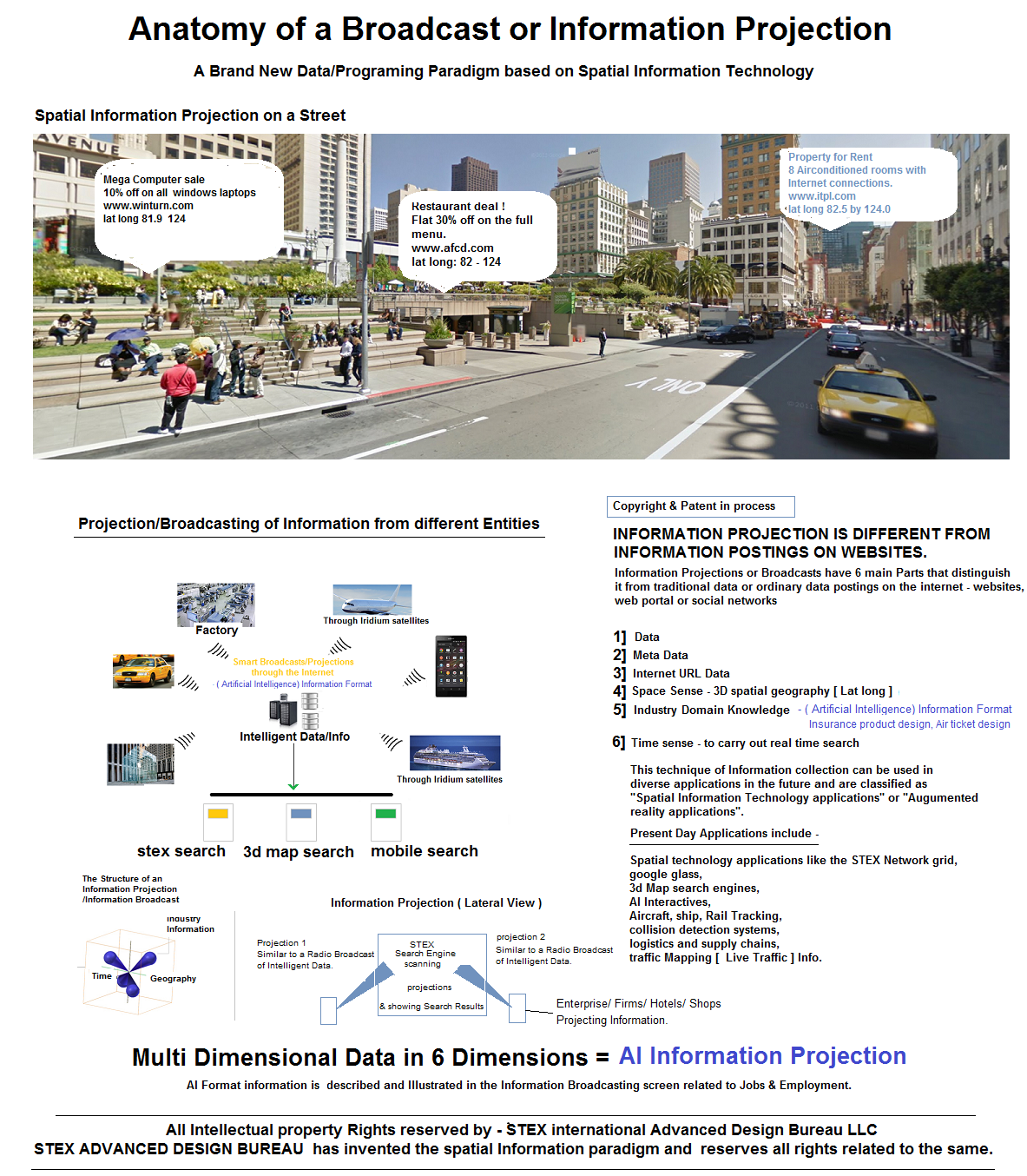
This Technology has Many Futuristic applications as shown in the Illustration above.
#2 Aircraft/Marine Rail Navigation& Tracking systems - using spatial Information Projection Techniques
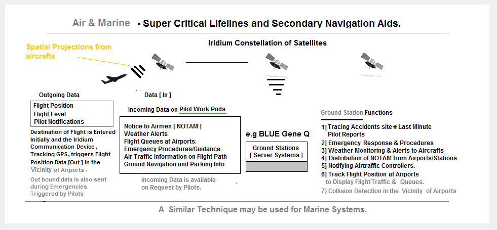
How is this Flight Telemetry Information Useful?
- Lets Pilots know of Exact flight queue's so as to reduce fuel costs during start ups.
- Allows Aircraft tracking beyond radar controls or ATC's upto the last mile parking bay.
- Displays Flight Queues at Viscinity of airports so as to calculate expected flight delays and Collision Risks, even during low visibility conditions
- Emergency notifications can be sent to ground stations with Engine and Flight parameters information.
- Allows ground stations to monitor Aircraft movement - as a Route Optimization function for fuel savings and Flight Delays.
- Note: For efficiency on the Internet satellites, each broadcast packet is compressed and sent to ground stations in burts every 1 minute, 2 minutes or 5 minutes. Ground stations operate in realtime mode on Inmemory Aircraft objects on Background maps.
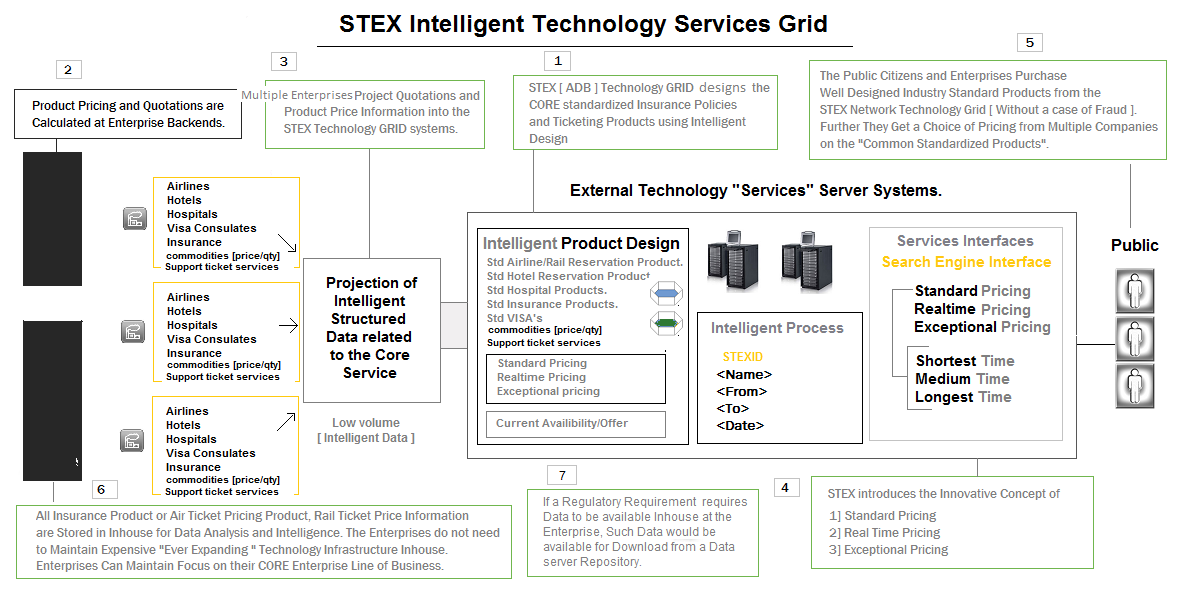
#3 Advanced Technology Grid Services :
The Primary Design Purpose of Building a Technology Grid Offering Insurance Products, Financial Products, Air Ticketing Facility, Rail Ticketing Facility, Hotel Booking Facility is to Standardize Idustry products.
Industry Products are Very Widely Heterogeneous in Design, so Every Insurance Policy or Financial Product in the Market has Varying Parameters, Clauses and Rules. The Products are So Many in Number that Consumers often Face the Challenge of Comparing Different Products with Many Variations in Terms, Conditions and value.
STEX Design Bureau aims at STANDARDIZING Insurance and Financial Products/ Air Ticket /Rail ticket/Hotel Reservation products by Designing The Core Product, The Policy and Rules and placing it on a Technology Grid server. Any Insurance Firm may Calculate The Product Quotations related to the Product and project the Information into the STEX Technology Grid.
This Saves Insurance Companies with a Huge amount of Ever Expanding - Inhouse Technology Spending, thus allowing them to Focus on their Core Line of Business. The STEX Grid System Integrated with the Technology Grid allows Members to Purchase a "Industry Standardized Product/Policy" with ease. The Same Applies to the Airline/Rail Industry, Logistics Industry and Health Industry.
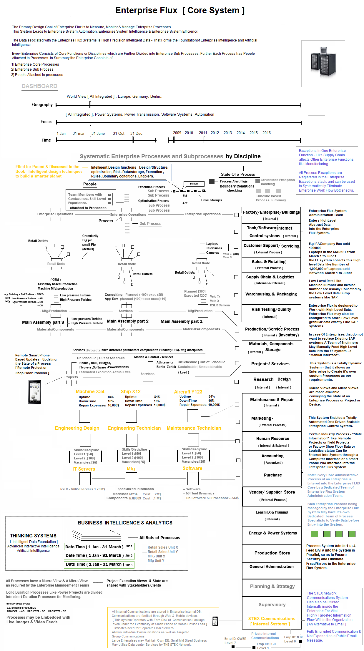
#4 Enterprise Control systems : Enterprise Flux
Enterprise Flux is an Advanced Enterprise Control System, also called an Enterprise Operating System. It is a Next Generation System that Introduces the Concept of a Totally Managed, Automated Enterprise – based on the principles of Advanced Enterprise Architecture, Spatial Systems Engineering, Enterprise Collaboration, Pervasive Information. It is Domain neutral, therefore it fits into any enterprise in any domain and allows effective & Intelligent Enterprise Governance. It is designed to work with Enterprises having remote divisions Remote site projects & Transnational Operations. It facilitates Measuring, Monitoring and Managing an Entire Enterprise from One Single DashBoard. It connects People Process and Product across the Enterprise, makes Enterprise Information Pervasive and creates a [ Fluid & Focussed ] Engineered Enterprise System. It is also designed to offer Artifical Intelligence Assistance [ Advanced Interactive Intelligence - A program designed to Collect Enterprise Data, Think and Provide Strategic/Intelligent Supervisory Insights and Guidance ].
What is the Working Principle and Foundation for Building an Advanced Enterprise Control System ?
Enterprise Flux is similar in working principle to SCADA [ Supervisory Control and Data Acquisition systems ] and works at a Abstraction layer above traditional Enterprise Process systems like ERP software and IT systems. In anology Windows and Unix systems run the Computer Hardware system, while Enterprise Flux runs Enterprise Systems. Note: ERP SYSTEMS like SAP collect highly detailed info like Invoice number, product numbers etc which makes ERP systems a Low level granular Data Dump. Enterprise control systems inturn work with High LEVEL Data that provides effective Enterprise Governance mechanisms/tools.
Enterprise Flux Systems may Collect Enterprise Process and Supervisory Control Data from Users through traditional computing Terminals or even Handheld Microcomputers like the STEX pad. [ STEX Pad are Connected devices and can be usd with ease at Remote Locations ].
ADVANCED ENTERPRISE ARCHITECTURE
The Enterprise Flux system acts as a Functional Control system, as well as a Reporting system to the Enterprise Work Force. ( This method implies that Individuals in the workforce don;t report to a Hierachially superior Boss, but report to the Enterprise Flux system Instead. Note: People and Heads of Organizations leave and move out, but the Master system control Enterprise Flux remains as an Irreplaceable part of the Organization allowing constant control of the Enterprise. All Enterprise Commands, control structures & actions are made through the Enterprise Flux System through Qualilfied Members and Administrators.

ADVANCED ENTERPRISE ARCHITECTURE - PART 2
Static, Aged, Large organizations may operate in a new "structurally designed Enterprise Structure/model" called the "Derived Enterprise model". A new Enterprise Division is "derived" ( from the Parent Organizations and Accomodates the Highest Performing workforce in the division" ). Senior Supervisory professionals act as Supervisors and facilitators at the Parent Division/Enterprise, controlling the Sub divisions. Note there could be More than 1 Sub Division to accomodate a large numbers product segments or Functional disciplines. E.g Sales division work for a Single division and sell for multiple Product Segments or services cohesively and act as an Intermediate cost center.
#5 STEX FCX Reality Compilers [ FCX Programing Language ] - For Dynamic System Programing - Theoretical design
Reality Compilers are a Special Type of Compiler that can can be used to Facilitate Building of Robust, Complex and General Purpose Software systems like - Next Generation Operating Systems, Network Protocols, Games Development, Enterprise Control Systems & Realistic Artificial Intelligence Systems. The FCX compiler uses a High Level programing Language called FCX. It Includes an Imperative programing model along with a meta data model and a functional programing model.
- FCX is a Visual Intutive Programing system with a Number of built in Programing
Models.
- Object Lifecycle Model
- Object DATA Model
- Object Functional Model
- Object Relational Model
- Imperative Programing model
- Object Interaction Model
- Spatial View modelling
- Virtual Fabric Memory store -non file system memory model
- Fluid datastore Model
- Object Life Cycle Model - Used to create,destroy and Clone Objects.
- Object Data Model Programing - Consists of Object Data Points and [ 1] Primitive
Datatypes like Int, Float, String, Boolean, Date time etc. 2] Abstract Datatypes
like: Array, Linked List, Lists, Stacks, Queues, Trees, Indexes. It may Include
Other special Data Types that allow easy System Software Development.
- Freescaling Structured Object List[] - Objects with Multiple columns and Dynamic Column datastore. [ Freescaling Data without creation of an additional object record ]
- 3D Array Object Data type - To Store Custom Datapoints like X,Y,Z Pixel coordinates, Lighting, Colour etc.
- Object Pattern Data Type[], String Pattern Data Type [] - To Store Patterns of Data.
- Time Stamp Datatype[] - a Dynamic Array of Time Stamps that are auto generated and Cannot be changed.
- Object State Stamp[] - Can be used to save the state of the current Object in a Dynamic List or File. A list of Object States may be used for Analysis. It May also be Incorporated into the Object Patterns Data Type for a variety of applications.
- Virtual Fabric Memory Address [ Main Memory | Flash Memory | Hard Disk | External Card ] - Used to Set Memory address of Objects in a Particular Disk Medium
- Geographical Location[], Space Coordinates[],
- CPU Core [] - For Parallelizing Operations &, Energy [] - To detect Battery energy Levels for Process optimizations
- Object Reference DataType[] - Is a File Pointer that can be used to Reference Objects and store them in Special Graph Data Structures or other Data Structures like Linked Lists.
- File Data Type[] - Used to Read or Create a Physical File on the Virtual Fabric Memory. These Files may Store Objects of a Custom Data Structure type and read Objects of a Custom Data structure - E.g. Like the Freescaling Object. This also allows creation, Modification and Storage of Open Standard File Structures.
- File Reference Data Type[] are Used as Physical File Pointers that may be stored as Linked Lists, Maintained in Transaction Logs and Indexed.
3D Array Data Type is used to set Object Structural/Design Boundary Points using the X,Y,Z Coordinates. The Polygons, Colours, Textures, Shading & Lighting Functions may be applied on the Data Points. Application areas for this this Data type is
- Game Object Programing - Which May be Dynamically Transformed through Structural Transformation Functions.
- Operating System Windowing Manager.
- Interactive Movie Programing.
- CAD - CAM - 3D Design Objects for Electronic for 3D Prototype Printing or Machining.
Patterns Data Types are [ 5,6,7,8,9,X Variable ] Data Point Patterns of [ Dimensions like - String of Words, Object Columns ] and are called Pattern Strings. A Strings of Words [Text] may be stored as Pattern string inside a Pattern List, with an Unique Pattern Identifier and this UniQue Identifier may be attached to a Complex Object Record as a Pattern Dimension for Facilitating a Pattern search. Indexes of Pattern Data Types may be created for these Pattern Dimensions or Normal Object Dimensions for High Performance Search Queries of Complex Contexts & Synthetic Data. Pattern Indexes/Lists may be build at Two Levels or Multiple Levels, with each Having a Different Number of constituent Data Points. Pattern Matches could be of the Type:
- Exact Pattern Match
- Synonym Pattern Match
- In Synonym Pattern Matches the Entire Input string is converted to a String of Representative Synonyms before creation of a Synonym based Pattern. When Searches are conducted for a Pattern we May use Both the types of Patterns for Finding a Record Match.
Note: These Pattern Matching Technique can be used to Map A Natural Language Pattern to the FCX Object Relational Patterns for Fluid natural Language Processing in Realistic Artificial Intelligence Interactives. Internal Mechanisms may include Converting a Natural Language String to an Object Pattern of Synonym ID's where a Synonym ID is an Unique Synonym ID representing a of Pattern of Synonyms of Words. The object Pattern of Synonym ID's is mapped to Pattern of Synthetic Contexts in the FCX object Relational World. Note: String of Words may be stored as a Single Pattern or an ObjectSet of Multiple Patterns.
Pattern Based Data Points can be used to Store a set Latitude Longitude Datapoints that Consitutes a Road. This Can Provide Accurate Point to Point Map Navigation and Alternate Traffic Routes when, Integrated to Artificial Intelligence Interactives. [ Note: Data Points can be collected by Driving a Car through a Particular Road ]
Data Types like Time Stamp[] May be Used to Store The Multipoint Process Time stamps, e.g. Aicraft Landing Times at a Specific Airport or delivery Time of a Parcel. Delays may also be stored as Time Stamps and Ultimately as pattern Datatypes and These Patterns could be used to spot Delays in a Process or Low Load Factors of in an Aircraft route.
Virtual Memory Address Data Types can be used to Create Tiers of Memory Within a Program. It Can be used to create and Manage Lists of Free Memory Blocks, that may be used for Purposes like Automatic Memory Management Processes and additionally for Physical File Storage & IO on Disks.
Geographical Memory Addresses may be used to Store Latitude Longitude and Height of an Object. Space Data Type may be used to store XYZ Central Reference Space Point of an Object - used for applications like Graphic Object Positioning on Screens depending on a Form Factor. An Object may use a 3D Array of XYZ space Points to create a 3D Object Data Structure. Other Application specific Dimensions like Pixel Colour, Lighting may be used in conjuction with the Space Points[] in a 3D array. e.g write an algorithm to capture all the distinct pixel points in a [ realistic picture ], and place each distinct color's pixel coordinates in a single linked list array of 3d objects. it may look like : Blue list - [1,2,3],[ 1,2,4],[ 6,7,5]...... green list - [5,2,8],[ 7,9,10],[ 46,77,58]......
CPU cores and Battery Energy are used for Parallel Processes allocations and VIKM type intelligent Process Scheduling and Energy Conservation.
- Object Function Model [ Explicitly Distinct Implicitly Coherent Factorized
Intelligent Design Functions ]. E.g. Design[ ], Execution [ ] etc, External Physics
Engines/Libraries [ ]. Note: EDIC Functions may be [ Public ] or [ Private ]. E.g.
A player Has the Ability to Initiate Action Functions like "Shoot [ ]" at enemy
which is classified as an Execution Function - "Execution.Shoot[ ]". Another Function
could be "Design.DrawTextures[]"
Note: An object may Constitute of Multiple Execution Functions, Graphic draw functions( state transform functions ), data points , optimzation functions etc. Storing Object functions repeatedly within each object may waste inmemory space therefore objects may store "pointers to the Function" in the Inmemory objects. These Object pointers point to the real functions, and in principle, is similar to code reuse in C++ (oops).e.g. Multiple game objects point to a single exec or draw functions. This could be achieved by adding a metadata attribute [Pointer] to any function in the Game object, in order to recognize that the function is a Pointer to the "Real Function".
Note: Data Points of the objects always remain within the object , because the datapoints represent the state of the object. These datapoints may undergo state transformations, allowing state changes of objects.
- Object Relationship Model - This design principle allows creation of Object
- Object & Object-System Hierarchial relationships, and is represented in the
system by an Object relational Graph Data structure. The Graphs are created during
Program Compilation but are dynamically processed and kept "upto date" to allow
"High Context" Object State Updates taking place in the system. Note: State Updates
are Handled by Object State Management Functions. E.g. In the context of a game
- weapons are child Objects to a Parent Player. When a Player drops a weapon, the
player Object's Weapons State is updated by accesing the object through the object
graph.
Objects with No Relationships [ Neutral Relationships ] are also maintained in the Object Graph. E.g. Collision Physics between two Objects with neutral relations. Priority attributes are Priorities attached to the Object Variables [ Dimensions ], to allow sequential ordering of Object Graphs, which would facilitate instant State Updates of objects, depending on the Priority Dimensions. E.g. In a Game Scenario, if Priority is Set on the "Space" dimension, and a Blast/Collision Occurs, the Nearest Objects to the blast/collision would need a State Update [ Collision physics ]. This would be possible through traversal of Object Graphs which are Sorted by Space or Distance and represent the actual Objects in memory.- Relations between Objects are Created by attaching Intelligent Metadata to them. This Process is termed Intelligent Object Life Cycle.
- All Objects and MetaData Attributes Have Names and an Identificaltion Code.
- The Objects are of the Type -- [ Simple Object | Complex Object | Simple Process | Complex Process | Intermediate System | Complete System | Organism ]
- Objects have Relationship Metadata associated between them -- [ Parent-Main | Child-Sub | Partner | Opponent | Friend | Neutral ]. Default Relation is "Null".
- The Objects have additional Metadata - [ Private | Public ].
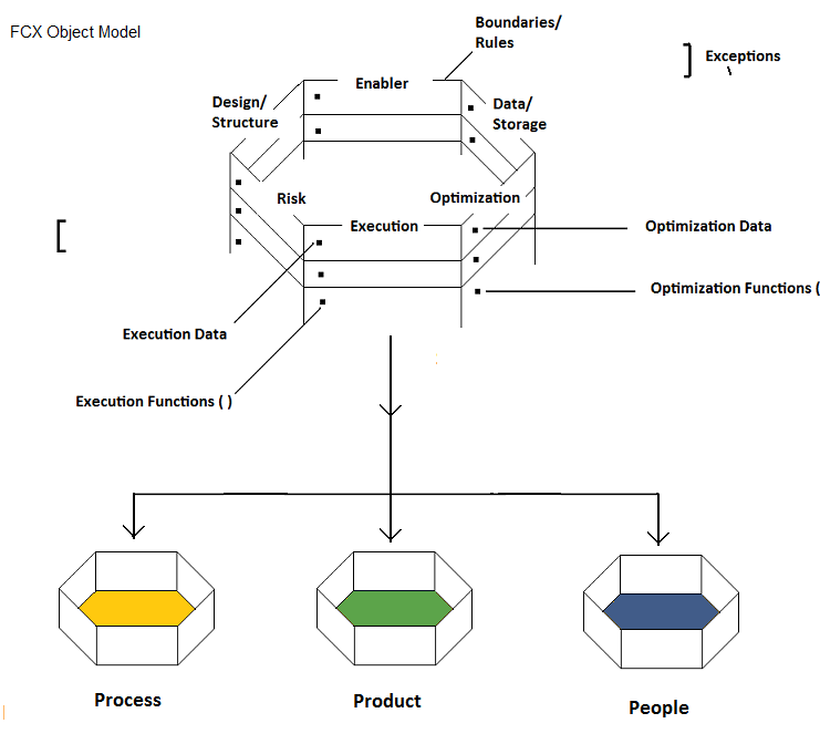
- The Objects have "Multiple" Type Metadata Points associated with the Objects - Simple 8 Point Matrix or 8 by 8 Intelligent Design matrix consisting of Types like [ Design ] [ Structure ] [ Data ] [ Storage ] [ Risk ] [ Enablers/Resource ] [ Optimization ] [ Exceptions ] [ Rules ] [ Boundaries ] [ None/Null ].
- They may have Inbuilt Object Lifecycle/State Level 2 Metadata types [ Medium, Measurement, Lifespan, Current Iteration, Current or Previous State, Priority, Parallel Tasks/Threads, Views, Current Location [From], Current Location [To], Created Time, End Time, Complexity Mode of Object/Process, Size or Scale of Object ]
- The Objects have additional Level 2.A Metadata like -- [ 1] Primitive Datatypes
like Int, Float, String etc. 2] Abstract Datatypes like: Array, Linked List, Stacks,
Queues, Lists, Freescaling XML Data List 3] Undetermined 4] Null 5] Custom Enumerations
like:
- Size: Small | Medium | Large.
- Duration Task: [ Short | Medium | Long | Unknown | Continuous ]
- FileTypes:Program Registry, Directory, File
- Current Location: From [ X,Y,Z ] to [ A,B,C ] Coordinate or File Location [ X to Y ] Memory address or Parking Bay 1 to 2. From and Two Locations may also be the same.
- Transaction: Voice, Realworld Handshake, Online
- Internal Storage: BIOS Memory, HardDisk, Main Memory, HighSpeed Cache
- External Storage - USB|CD|DVD|Omega Drive or Physical World Storage: Storage Shop1, Shop2, Godown etc
- Mode of Object/Process: Simple Functions | Standard Functions | Complex Functions | Trail & Error Functions etc ]. Note: an Object be a Complex Process consisting of Multiple Transaction Functions or Multiple Complex Functions.
- Size or Scale: [ Very large | Large | Medium | Small ] -
E.g. Large Gas Turbines, Mid sized Gas Turbines | Small gas Turbines
E.g. Large Video File | Mid Size Video file | Small Video File - Priority: System | Very High Priority | High Priority | Medium Priority | Low priority
- State: OnSchedule | Delayed | Exception | Active[ Unknown]. Note: Detailed Custom State of a process may be obtained by writing Execution.State[] functions that collect datapoints to show detailed state.
- Objects may have Optional Customizable Level 3 Metadata called Domains -- [ Homosapiens | Animal Species | Aviation | Computing Hardware | Software | Operating System Memory Management etc. ]
- The Metadata attached to objects are Synthetic Intelligent Data Collection/Patterns to convey a Sharp Context about the Object. The Context Synthesis happens by Combining Attributes aross levels of MetaData like [ Organism + Opponent + Private + Lifespan + Virtual Computer Game Player ]. Additional MetaData May be Added as Datapoints to the Object as per Requirement of the system E.g. Body Damage or Energy Levels etc.
- All MetaData Values may be Stored as Enumeration OPcodes, therefore they would, Occupy Very Little Memory and Database Space. It may be Noted that the Objects are in memory Objects, however access to the Objects and State Changes are Facilitated through the Object Graphs [ Pointers to the Objects ]
- Imperative programing Model - They are essentially Object State Management
Techniques to allow Cascaded Triggered State change of Related Objects in a Systems
using "Object Relational Graphs". The object graphs are continuous functions that
reorder themselves to maintain an ordered list of High Context Object Pointers.
This allows Predictable "Paths" for State change of nearby objects by another Related
Object. E.g When a System Event occurs, High Context Objects are affected but other
Objects remain unaffected. In the Example of a Game Play -When One Player explodes
a Bomb, the Bomb Explosion Event may affect the State of Nearby Objects, while distant
Objects may Remain unaffected.
The Object Relational graphs may be generated from the relationship Metadata data values & and are Continuously sorted according to Dimension Priorities, so as to Facilitate an action/state updates of High Context related Object Variables. This Programing Paradigm is called Programing with Side Effects, where "ONLY" a small set of "Related cascading Objects" undergo state Change, when triggered by an object/system event, thus forcing nearby related objects to undergo state change. The state change of "Objects" or "Processes" or the "Entire system" may finally translate to a change in system behaviour on the graphics screen.
Note: Object Lifecycle Functions are used for creation, destruction and duplication of Multiple Objects, while State Functions are used to control realtime "States" of objects. Every Object May Have a Function marked with a Attribute [ Event ] and may have Conditional rules of State Data, which helps in Triggering Events. When The State of an Object is Changed in a Manner, that it matches the Conditional rules of State change described in the [ Event ] attributed function - a sequence of cascading state change functions may be triggered into nearby related objects. This Happens as a Sequence Chain in a Sequential manner, so that no deadlock conditions arise. This implies that State updates of objects through object Relational graphs are sequential processes instead of parallel processes, however Functions within the object, that trigger a state change, may be executed in parallel. In principle, this resembles a Sequence of parallel tasks. [ It is similar to the Physics principle of Nuclear Fission ].Note: Whenever the Object State Data Changes, the Functions attributed as [ Event ] are checked for an Event Triggering Boundary Condition. If Conditions are Valid an Event is Triggered.
In principle this Compilation technique leads us to create Dynamic software Systems where, the Quantum state of a System evolves gradually or varies, based on the actions of Individual Constituent Objects or Players of the system. This dynamic system has no Fixed Final outcome or state. The Immediate Next "States" of the System are however predictable based on the Current Action of the objects or Actors of the System.Example:Processes within an Enterprise are "interrelated" to other processes. A Component Storage Unit may Have the Capacity of 100 Components. When a Component is removed from the Storage Unit the Number of Total Components is checked and if low in number, an event may be triggered to to another Related Parent Storage to supply it with Further Components. On Unavailibility of Components, a Process Exception May be raised and Recorded into Dynamic Exception Handling Stack Data Structure. The Flow of Exceptions across processes would enable Systems to Point at the Error Source, so as to enable corrective Action. Exception Flows may be [ Intra Process or Inter Process ]. Example : Manufacturing Exception May lead to a Component Storage Exception and this may further lead to a Supply Chain Exception. These Patterns of Exceptions can be analysed for Smoothening a System Workflow.
E.g 2: EARTH is a Dynamic System. It's Constituents are people, enterprises, processes .State changes in People and enterprises or processes leads to cascading state changes in other constituent elementsor nearby objects ( other people, other enterprises etc ) and this leads to different "Quantum State" outcomes in the Earth system. ( Think !- about economic conditions Like Recessions )
Advanced Artificial Intelligence Interactives may also Quickly Trace Exceptions and help in Trouble Shooting of Problem Areas, leading to Fully Automated Enterprise Systems.
- Object Interaction Model - COLD Machine Technique - Interactions are "Process
Interactions" between two Objects [ or Two Processes ]. This Interaction is Invoked
by One Object Changing the State of the Next Object by calling the Second Objects
Internal Method. The Internal Method may choose to change the State change of Invoked
Object by Rules and Logic and this state Change may cause a Cascading set of Event
Triggers that Change the State of Other Related Objects [ e.g A Domino ].
Cold Machine Technique - This Interaction Model Saves Game Objects from Going through External Game Loop Cycles and Internal Object Game Loop Cycles, listening for Events. Out of Context Game Objects may need to be ready for State updates, but may save CPU cycles by allowing only Chained Triggered Events. Note: Saving CPU Cycles in Mobile Devices Saves Battery Life. Some Processes like Graphics Rendering may need to be run Rendered Continuously, Though Background Processes may Run "Cold". On Larger Server Systems on Public Networks A Huge Amount of server CPU Cycles may be saved, adjusting to User Demand - Inturn Saving Energy Consumption. CPU Strategies may involve shutting down maximum CPU Cores while keeping a spare core active - for a Responsive system Design.Intelligent Operating Systems & FCX Programs The Virtual Fabric Memory Filesystem technique offered by FCX has been Described in sections Below. , offers a Facility of Accessing a Mixture of Main Memory, Flash Cards [ like XQD, Compact Flash Cards ] and Harddisks in Programs. Next Generation Operating Systems and other Programs written by using FCX Compilers can use Intelligent kernel manager Techniques to, use cheap non electricity consuming - Flash Card based Virtual Fabric Memory [ As a Buffer memory for Idle system condition/state ], while Putting Hard Disks to Idle. With Drop down in Process Loads - using the cold Machine Technique, General Purpose Programs may also run and reside in Main Memory while Hard Disks are set to Idle. On Increase in Process demands Hard Disks could run at Max Speeds. This Technique would Drop Down General purpose machine & Datacenter Energy Consumption needs.
- Parallel & Sequential Model - This system may be designed for Automated
Parallel or Sequential Execution of Functions of an Object, with the Default Functionallity
being Parallel Execution. Every Sub Function of a Complete Function within an Object
may be Described by an Attribute called [ Sequential | Parallel] to facilitate Parallel
or Sequential Exection of the Functions. The Compiler has the Internal Inbuilt Mechanism
to intelligently handle Parallelism, by tracking callbacks. The Compiler would allow
Programs to enable Parallelism by passsing on Information about total number of
Processors and Processor Cores. This Implies that Aprogram Created with FCX would
Autodetect CPU Cores on a Computer before executing a Parallel Execution Strategy.
No there may be No Explicit Threading Libraries Needed to Execute Parallelism.
- Example 1: Five distinct DB Fetch queries may be run in Parallel and subsequently Merged in a Sequential operation
- Example 2: A Game Object May Involve Automatic Parallel Execution of Execution Functions and State Changes. Graphics Rendering Functions may Run at System Level.
- Spatial View Modelling - Views are Functions that may generate Views/Perspectives of an Object or a System e.g. [ Objects, Process, Total System ]. Total System Views may Consist of: [ Priority 1 Processes, Priority 2 Process ] based on The Process MetaData. Other Views May be Of Custom Types like 360 Degree Stitched Panaromic Views. Another Example is the "STEX GRID search" displays complex views of data projected as Spatial Projections. Finally, Some Views may be Complex Rendering Views generated during Game Play. Games and Windowing Mangers may Use the Technique Pixel Lighting of Objects and Scalable Vector Graphics to Render Images on the Screen [ For Any Form Factor - Based on the Reference X,Y,Z Axis Values of Objects. ].
- Virtual Fabric Memory
The FCX compiler uses a [ Virtual Fabric Memory ] System to allow Objects & Processses access to Memory. The system May demarcate Memory Zones in the Virtual Fabric Memory - High Speed Memory, Flash Cache memory and Hard Disk Memory so as to allow High Level Objects/Processes to use specific Processes to run in Specific Memory Zones.
Operating Systems may run Dedicated Processes that Move Objects from One Memory Zone to another as a Part of the Memory Management Process. System Processes may have a Fixed Memory Zone and Other Objects may be allocated to High Speed Memory Zones and Deallocated to LowSpeed memory Zones as a Part of the Memory Management Process of an OS or a Program.
Note: Internal Working Mechanism of the Compiler is that, when Working on Existing Operating Systems like Windows or Unix, It Detects Memory Addresses for the Main Memory and Memory addresses of Other Devices though their Drivers to Create a Total Virtual Fabric Memory, with Demarcated Memory Zones. The FCX Compiler may also Detect Total Number of Processors and Processor cores and Additional Hardware Device Info. The Advantage of the FCX Virtual Fabric Memory Technique is that it allows a Programing Model to use Demarcated memory Zones, which is not offered by present day General Purpose Operating Systems or Programing models in Compilers.
In the Program Model an Object may use the Virtual Fabric Memory using Enumerations like: Fastest Tier 1 Memory, Tier 2 Memory, Tier 3 memory etc. The Developed Programs autodetect Tiers of Memory Available in any System and make available the best Mmemory Options for the Program to Utilize. If the Computing System has additional Memory Cards like XQD cards, the Program would autodetect the High Speed Memory and utitize it to speed up Programs. The Advantage of Such a Model is that Hardware Technology Innovations [ Faster Devices newer Devices ] may be Accomodated into Existing Hardware Systems incrementally as per requirement without the need for a Full system Overhaul. Newer Systems may have a Wide Variety of Configuration Options available [ Low End to High End Machines ]. The Hardware appears Tiered and Abstracted to the Operating System or the Programs - for them to Make The Best utiliation of available Resources. E.g A Program may Commit a Transaction on a Flash Memory if available and then transfer the data to a Hard Disk for a Final Commit.
Virtual Memory Fabric Based Physical File Storage - No File System !
The FCX compiler Uses No File system to Store Physical Files or Objects. Every Object Whether a Video File or a DataBase Record is stored using the Virtual Memory Fabric [ HardDisk Demarcated Zone ]. The Object Created from the Compiler or the Program may be stored as a File using the Virtual Fabric Technique. The Pointer to the Main File [ File ID and Name ] are Stored in Tier 1 Zone of the Virtual Fabric as Ordered Lists of a Particular File Type. This File Pointer Has the File Start Address and File End Address File, pointed to a Tier 2 File Storage Zone. The File start Address and File End addresses are Virtual Memory Fabric Addresses containing the Actual File. The Ordered Lists may be traversed by Search Algorithms to locate the Start & End address of the File, to fetch the Actual Physical File. This Virtual Fabric Address can be reached Directly on the Hard Disk, for a High Speed Buffered File read into a Special Tier Main Memory, from where the Data may be accessed by the CPU. All Data belonging to a Particular File are Stored in Contiguous Virtual Fabric Memory Locations.
A Virtual Fabric File "Dynamic Lists [ Where Pop Happens at One End and Push Happens at the Other ]" Stores the Current Contiguous Blocks of Free Virtual Memory Addresses along with their Size [ Contiguous Blocks May be greater than a Reasonable Size of 3 Mb to be Placed on this List ]. When a New File is to be written, an Algorithm Finds the Most Fitting Contiguous Location to write the File, and it's Start and End addresses are updated to the File Pointer. When a File is deleted the [ File Pointers ] are Updated. The Immediately Freed "File Start" and "End" Address Locations are updated to the Virtual Fabric File "Dynamic Lists" as a Contiguous Free Memory Block [ Along with Size of Block & only if Block is greater than 3 Mb in Size ]. A Second Minor "Dynamic List" of 1000 [ Customizable ] Memory Addresses with Contiguous Blocks of Virtual Fabric Memory upto the size of 3 Mb are also Maintained. This Minor List is used to Write Files of Small Sizes. A Dedicated Process May run to Rearrange Small Blocks of Defragmented Files to make Them Contiguous. This Virtual Fabric Based File Pointer Based System, is a Fast Technique to Read Files from the Disk.
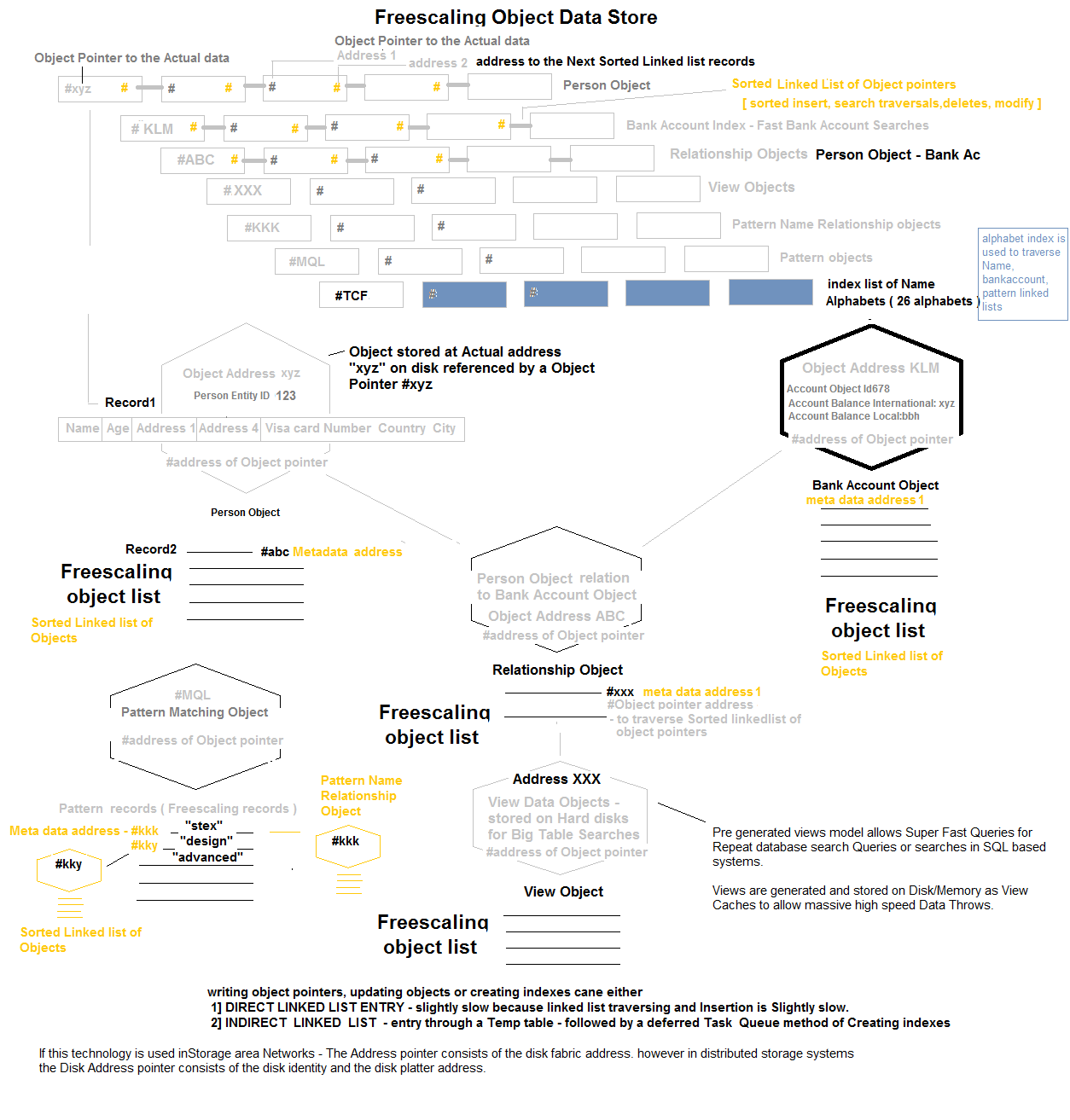
Fluid Data Store
The Internal Construct of the STEX Fluid DataStore is Described as Follows. Every record in the Fluid Datastore may be Represented by a Single File, and this File is represented by a File Pointer. The File Pointer is Stored as a Ordered List Object in a Tier 1 zone of the Virtual Fabric [ Hard Disk Zone]. Records may be Added, Deleted and Searched on the List by Maintaining an Ordered Ordered List. A File Index may also be maintained for High Speed traversing of the Ordered List to Locate a File. This Helps in Extremely Fast Datastore Record/File Pointer Searches, Which lead to the Actual Data address Location. A separate Ordered List May be Maintained for Other Dimensions of the Object that are Frequently Used for Searching a Record. E.g The STEX Grid ID or an Email Address. E.g If a PersonID has Multiple Bank Accounts and Each Account has Account Records, the Datastore Allows Direct Querying of Bank accounts Object or Accounts Records as The PersonID is stored as Associated MetaData with the Bank Account Object.[ Parent Object and Metadata Objects are Separate and Metadata Objects have Parent Objects id's as Metadata atatched to them - thus Querying does not Involve hierarchical Object Relations in Search Queries ]
Every Object in the STEX Fluid Datastore is Alloted a Dedicated Virtual Memory Fabric Space of Minimum 1 Mb. [ This Size is Configurable depending on the Object Size to be Stored ]. The Maximum Size May Have no Upper Limit. This Implies that When Small Objects or Files Are Written to the Disk They Occupy a Minimum of 1Mb, even though the File Size May be less than 1Mb. A Freescaling Object Record Belonging to a Person may occupy 0.5Mb of Data, while 0.5Mb of space is available for Future data addition. When File Size Updates are Larger than the Total Available Space for the Object, the Entire Object is written into a New Virtual Fabric Location with the Addition of 0.5MB Free space for the Future use. By this Technique Maintaining a Record of 6.5 Billion People on this Planet would require only 6.5 Petabytes of Average Total Datastore Memory space. This Technique Involves Very Little Fragmentation and may additionally be healthy for Flash Based Storage devices which suffer from Constant Writes. Note: Normally Transation Based Objects may require only 10 to 50 Kb of Object Dataspace instead of the 1Mb mentioned. Large "Contiguous & Free" Virtual Fabric Space Addresses are mained in Lists for the Purpose of New File Additions or File Relocations.
A File Transaction Log is used to maintain Milestones of a File stream being written to a Disk or is being relocated from one disk zone to another. Transaction Logs are maintained to check File Integrity in case of a Power Failure, and are always checked during a System Startup to check an improper Disk shutdown during a filewrite process.
Note: A File stream being written onto a Disk Consists of a Set of Milestones which are maintained in a Transaction Log along with a Milestone Start and End address and an End of File Descriptor. A large file of 5 Mb May consist of 5 Milestones, each with a Start and End address. A small file of 2 bytes May have 1 Milestone with a start and end address.
If the Transaction Log is Intact the Ordered List File Pointers and Contiguous Free Space Lists may be Updated to the Disk. In Case of a Power Failure Scenario, Between a File Write Process, The System may check the Transaction Log for Data Integrity of File Milestones. If Milestones are in the right Sequence and the transaction log has a File end descriptor, the Linked Lists and free contiguous File lists are updated, else the stream of Bytes on the Disk are updated into the Ordered List as a Broken File, which may be deleted if Required. The Same Principle is used to store Files in Storage Area Networks instead of a Small Disk.
Massively Parallel File or Database Record Reads & Failovers
Finally, Object Record Writes or File Writes may Happen Parallely only Limited by the Disk IO Capacity. This system Design principle Allows Fluid Datastore to Run Disk Replication Strategies that are extremely Fast - Where a File Write or Record Write Process involves Copying one Set of Bytes from One Disk Area to Another, without the use of a File system based Disk Replication. In such a Strategy The File Pointer may have Address locations of two or More Replicated File Data, Located in Different Disks Zones. This Technique may be used for failovers. During Parallel Disk Writes - The Transaction Log is Verified before selecting a Start Address for Contiguous File Writing because There may be a Possibility of Contention between two Disk Writes trying to Occupy the Disk Zone [ Therefore in Principle the Transaction Logs are only Disk based dynamic lists that hold the Start addresses for every Current Parallel Write Disk operation ]. Duplicate File Pointer Linked Lists may also be stored for Security and Robustness and Scalability [ by allowing Parallel Data access from Disk Zones or Disk Machines through Loadbalancer algorithm - Higher IO Capacity ]. This Technique allows Massively Parallel Record Reads and Writes on a Disk or a Storage Area Network, by using Infiniband connects for high speed IO.
The Fluid Datastore Facilitates Pre-Generated [ Pre Sorted ] Data Views ( View cached on a Hard disk ) and Data Models that allow Allow Fast Queries for Pre Determined Repeat search Queries. Fluid Datastore also facilitates Data Caching or Data View Caching for Repeated Searches. This Cache may be on disk or in Memory and removes the need for a separate Inmemory Caching system or a Key Store.
When Running on Proprietary File Systems of Operating Systems like Windows - the FCX based Programs Mark Certain regions of Hard Disk Space for Exclusive Virtual Fabric Based Usage - Similar to a Disk Partition.
#6 View Caching Technology [ Pre Sorted ] for SQL/NoSQL based Database Systems.
This model allows Super Fast Queries for Repeat database search Queries or searches in SQL/NOsql based systems, which do not have the Technology concept of a "pre-generated Views -( View cached on a Hard disk ). The Existing Technologies create a real time view of data,in memory.
Presorted Views are generated and stored on Disk/Memory as large View Caches to allow massive high speed Data Throws. If these features are built into SQL databases - they would provide extremely high speed data fetches for Big Data Queries ( Queries with Large Data Results ). This technology feature makes sql/No sql server's fit for "large throw" data search applications.
#7 VIKM - Operating system technology
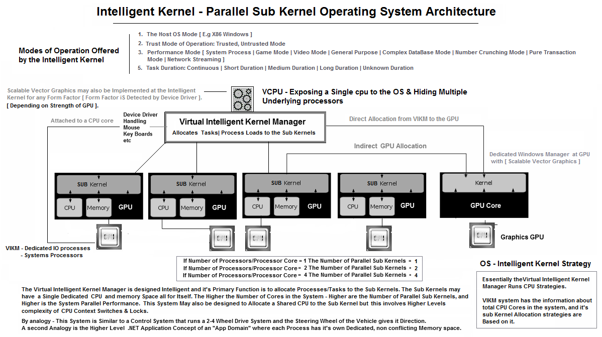
Intelligent VCPU Kernel Design - For Operating Systems, Hypervisors ( Solving the vertical scalability problem ).
The VIKM Exposes a Virtual Central Intelligent CPU to the Operating System, but Runs Parallel Kernels to Parallelize Tasks below. The Intelligent CPU is similar to a cpu driver which exposes virtual CPU's to the Operating system. Present day hypervisors have already shown us the technology of vcpu for VM's. If A single VCPU could hide multiple hardware processsors, server software licensing costs could be dramatically reduced. This allows vertical scalability of VM's. Application areas are..
The VCPU Interals detect number of Cpu's & CPU Cores. A user mode driver allocates threads to a Scheduler, finally allocating the thread to a Processor core for Highly parallel software execution.
- Hypervisors- as an Integrated VCPU Hiding Multiple Underlying processors.
- Operating systems - AS an os cpu driver.
The Operating System may allow Running of Programs in Different Modes which is Handled by the Intelligent Kernel Manager. The Kernel Manager also provides Modes Like:
- The Host OS Mode [ E.g X86 Windows ]
- Trust Mode of Operation: Trusted, Untrusted Mode
- Performance Mode [ System Process | Game Mode | Video Mode | General Purpose | Complex DataBase Mode | Number Crunching Mode | Pure Transaction Mode | Network Streaming ]
- Task Duration: Continuous | Short Duration | Medium Duration | Long Duration | Unknown Duration
The Operating System Has an Additional Highly Secured mode for Program Execution. This is Facilitated by Right Clicking the Program and Running it in a Untrusted Mode - Which runs a Program in a Readonly Mode and Does not allow Change of System Files and or Creation of Files and Folders. The Implementation is as simple as Adding a Process Parameter [ Metadata ] to the Executable - E.g. Untrusted Mode | Trusted Mode, and sending the Parameters to the VIKM. Next Generation Operating Systems like STEX [ Operating System ] may run the Secure Mode Processes in a Readonly Exclusive Parallel Kernel Process. When a Program has not been trusted by the User or Administrator, it may always run in the Default Untrusted Mode. The Process parameters [Meta Data] are Stored and Passed using the STEX Intelligent GUI Mechanism described in the Last Section. This Technique Makes Operating Systems Far More Secure and Virus Free.
The Operating System also has a Performance Mode Parameter for Program Execution [ Game Mode | Video Mode | General Purpose | Complex DataBase Mode | Number Crunching Mode | Pure Transaction Mode ] and the Task Duration Parameter [ Short | Medium | Long | Unknown | Continuous ] This may be used to Decide the Memory and CPU allocation Strategy for Programs. This Mode allows us to build Dynamic Sub kernels/Processes that may Increase CPU cycles and Memory Boundaries Dynamically - Depending on the Need of the Application. The Mode of the Process may also be Passed as Process Parameters [ MetaData ] to the VIKM. This Mode may be used in conjunction with The Trust Mode.
Intelligent Graphical User Interface.
Traditional Operating System Interfaces are "EyeCatching", yet "Dumb" Interfaces that merely handle Graphical Inputs and Outputs. The GUI itself Does not have any Built in Intelligence. STEX GUI is a Next Generation "Professional" GUI Terminal /OS-Interface/Skin that has Intelligence built into the GUI by addition of Process MetaData. The Built in Intelligence may be "Security-Trust Parameters" and "Performance Parameters" or "Task Duration Parameters" for Operating a Program. The STEX GUI Terminal/OS Interfaces may have Process Parameters or Process MetaData, attached to the Interface Desktop Items/Icons/Objects. The GUI may use a Specially Customized Windows Manager Attached to the Operating System core like the [ VIKM ] and Pass Crucial Strategy Parameters to it.
#8 [ STEX - Quantum Ballistic Magnetic Drives [ Integrated High density - Memory + Diskdrives ]
Traditional Hard drives Include a Read/Write Head that reads Data from a Magnetic Spinning Disk. The Disks Rotate at Rpm of 5400 to 15000 Accessed by a Head. This Technology Involves Mechanical Wear and Tear thus reducing Life spans of Disks. Disk Drives are also limited by Mecanical Speeds of Disk Rotation. Additionally, Traditional Harddrives use Random Data Access Technique to access data, which is a Slow & Inefficient Process. Quantum Ballistic Magnetic Memory is a Direct Data Access technique with Extreme Bandwidths. Quantum Magnetic Memory Disks may be Constructed by a 4 layered Structure as follows.
- Active Matrix Thin Film Transistor Layer - Pointing to a Directly Accessible Memory Address through Matrix Based Electric Circuit Lines.
- Thin Film Sheet of Merged Read/Write Heads [ Consisting of Inductive Writing Head + a GMR/MR Read ] - To Read and Write Bits on From/To a Magnetic Medium.
- A Thin Static Magnetic Storage sheet [ Film ] [ which Does not Spin like in a Regular Hard Disk ].
- A Shield Layer - Allowing construction of Multiple Layers of Magnetic Medium Storage medium to operate without interference
- The Active Matrix Electric Transistor Layer is placed over the layer of a Thin Film
of Read/Write Heads which is inturn placed over a Layer of Magnetic Medium.
_________________________________ - These layers are Parallel sheets and have [ One to One ] connected elements. This
implies that a single Transistor on sheet 1 - has a Corresponding Read/Write Head
in the sheet 2 and has a corresponding bit in the magnetic medium sheet 3. Since
these sheets are matrices, each transistor represents a Memory address bit. Multiple
Bits may be accessed in Parallel at any Given Point of Time.
_____________________________________ - The Layered structure allows Extreme high Disk Densities, in a Very Small Form Factors.
The Disks may collated to form Larger Storage Fabrics to accomodate a Datacenter
in a Box.
____________________________________ - Twin Transistors Mode of Operation.
_____________________________
Note: The Entire Magnetic Memory Structure may also be Designed without a Transistor thin film Layer. The Read/Write Mechanism may be controlled by the Matrix based IC lines attached to the Merged Read/Write Heads, that sense and write Magnetic Information directly to the Magnetic Medium as Bits.
_________________________________
This Design However may Include a current amplification Transistor attached to the Heads for enhancing the strength of Write Heads at an addressable Node. This allows Main Circuit electric Lines to work with low Current while Higher Currents may be required for the Magnetic Inductive writing Mechanism. The Read/Write Heads are also attached to two Storage Bit Transisitors. One Of the Storage Bit transistors with a Co-Capacitor, is attached to every Read/Write Head Becomes a Source of Virtual High Density Main Memory that can be refreshed in Cycles, to Maintain Data State - also called as "Active Hot Memory". "Cold" SRAM type flip flop Transistors may be used instead of a [ Transistor + Co-Capacitor ], as SRAM Transistors do not require State Refresh Cycle Techniques - also called "Active Cold Memory".
_______________________________
The Second Transistor is used to read & write Data from/to the Magnetic Layer. A Twin Transistor Technique is used because The First Set of Transistors acts like High Density Main active [ Hot/Cold ] Main Memory, and may undergo Transformations by CPU Instructions. The Second Transistors may hold the actual realtime Reflection of the Magnetic Drive bits. The Design of the QBMM may vary depending on the Types of Transistors used. Multiple Strategies may be used to store data on the Second Transistor as follows :- Magnetic Disk is accessed only when a Data Read is required. A [ Simple - Extremely cool ] transistor is used to store the Value, that may be Quickly accessed by Processors and Controllers.
- The Entire Magnetic Disk may be Read in One Cycle into the corresponding [ Transistors and Co-capacitors ], which are Maintained "Hot" by using fast/slow Refresh Cycles similar to RAM. Due to heat Considerations, these transistors may be placed in a parallel layer with Exposure to a Cooling Surface. Slow refresh Rates may lead to slower response times, but seek times may be faster than the previous - Extremely Cool Technique of Disk Access.
- The Entire Magnetic Disk may read in One Cycle into "Cold" SRAM type [ Flip Flop Type ] Transistors, that do not require State Refresh techniques. [ Size & Space relative requirements relative to Read/Write Head may be a Consideration therefore SRAM type Transistors may be accomodated in a parallel layer to the R/W Heads ]
- The Matrix Integrated Circuit design may have the ability to Selectively modify only a Small or Large or Entire [ Patch/Series ] of Magnetic Memory Addresses. Patch memory Reads may Involve either the active Main Memory Transistors or Hot/Cold Disk Drive transistors, which inturn Modify the Magnetic Medium, as per requirement of the application.
- The Lifespan of a Quantum Balistic Magnetic Drives may depend on the Type of Transistors embedded in the Thin Films, therefore Drives may be designed to be General Purpose or Exotic High Performance Drives.
- The Quantum Balistic Memory Technology allows Placing the Entire Hard Drive Content
to the Active [Hold/Cold] main memory or [Hot/Cold] Magnetic Drive memory, in One
Read Cycle, and thus allows Computing Processors, access to the Entire High Density
Main Memory for Extreme Quantum Computation Needs, of an Application. This Implies
that a Quantum Magnetic Disk of 1 TB may Provide a Computing System with
- 1 TB of Active [ Hot/Cold ] Main Memory
- 1 TB of [ ExtremelyCool/Cold/Hot - Volatile ] Disk Memory Replica/Reflection
- 1 TB of [ Non volatile ] Magnetic Disk Memory
- There may be a Three Transistor Technique used, where one transistor is used as
active memory, the second as a Hot/Cold Transistor Magnetic Memory [ a Hot replica
of the Disk ], and a Third Simple Transisitor used to Write data to disks, and update
Hot/Cold Transistors after the write.
______________________________________ - Quantum Balistic Memory Addressing may be Designed, to Match CPU Memory addressing Standards - 64 Bit, 128 Bit Addressing etc.
- Hot Drives may require - Cooling methods, while Cold drives may not require cooling methods. Extremely Cool and Cold drives may be used for personal computing while Hot or cold drives may be used for or Server Computing [ e.g Hot drives may be faster than cold drives but may be water cooled. Also note the surface area of the drive may be very small and the Form factors would be very compact, therefore Cooling Techniques may not reguire Extensive Designs. The Compact Design would Eventually Bring Datacenter Cooling requirements down to near negligible levels ].
- Next Generation Computing Systems may Integrate the Entire Set of Processors and Quantum Balistic Magnetic memory to create Advanced Integrated Systems on a Chip.
- Finally an analogy to Quantum Mechanics: Data Exists as a Particle [ Transistor ] and a Wave [ Magnetic Memory ].
Quantum Ballistic Memory may be designed in Numerous Electronic ways:
- Main [ Execution ] Processor may directly access the Quantum Balistic Main Memory, through a Controller.
- Multiple [ Execution ] Processors may directly access the Quantum Balistic Main Memory, through Multiple Controllers.
- Dedicated [ Data ] processors may be embedded in the Quantum Balistic Disk - The dedicated [ Data ] Processors may Provide Continuous streams of Memory Bits from the Disk or Memory to another [ Execution ] Processor through an Intermediate Cache and an interconnect. The Twin Processors may be synchronised for a Delay Free Computation. E.g In some cases the Execution Core may perform Heavy Computation Tasks on a small amount of Data, therefore in this case the Data processor may be designed to be slow to avoid wasting Data CPU cycles. The Execution & Data Processors may have Internal Caches to store Instruction Pipelines and Intermediate Processed or Fetched Data. Quantum Ballistic Memory Addressing may be Designed, to Match CPU Memory addressing Standards through controlllers - 64 Bit, 128 Bit Addressing.
- Multiple Dedicated Data Processors may be attached to the Disk - Reading parallel Data and supplying it through an Intermediate Cache, to other Execution CPU's through an Interconnect.
- Contemporary/Legacy Cards & Interconnects may be attached to the disks to allow access of data. E.g - SATA, Fibre Channel Interfaces, Infiniband Interfaces for Transfer of the Data. The Bus Speed of the Interconnect may control the Speed of Data Access.
This Technology May also be Used in Place of Volatile Electronic Memory Technologies like - Random Access Memory & Flash Cards in Many Computing devices. This Technology is only Limited by the Life span of Magnetic Storage Medium, Read Write Heads and Transistors.
By Principle, Random Access Memory are Volatile Memory and have Limited Bandwidth compared to the CPU bus. By Contrast, Quantum Balistic Magnetic Memory are Both Volatile and Non Volatile in Nature. The Data on the Magnetic Disk is Non Volatile Memory and the Data on the Transistors is Volatile Memory. Quantum Magnetic memory may have unmatched Extreme unmatched Bandwidths, only limited Speed of Semiconductor Based Processors accessing them. This May also generate Heat, therefore Controllers and Data processors may be designed to run a low clock frequencies and Large Number of parallel Cores/Channels.
Quantum Magnetic Memory consume Extremely Low Power that Enable construction of High Performance Computing Systems [ Servers, Computers, Micro computers and Mobile Devices ]. The Quantum Balistic Magnetic Memory Removes the Wide Gap in Computing Speeds between Processors and Slow Data Access Devices like Harddrives. This Memory Technology takes Computing Systems to Ultra Speeds, Ultra Density, Ultra Scale, Ultra Reliability and Ultra Energy Efficiency, and allows Next Generation Computing Systems to exist as an Advanced Integrated System on a Chip.
These Memory Drives may have little Scope for Errors, because they constitute no Moving Parts. Smart Memory Monitoring Technologies may be Easily Incorporated into these Drives to Detect Errors that may be induced due to Prolonged Usage. Errors may be Simple to Monitor at 3 Possible Points of Failure:
- Failure of Transistors
- Failure of Read/Write head
- Failure of Disk Magnetic Retentivity
- Failure at Any of these 3 Points would indicate a Bad Disk address. This Bad disk address may simply be removed from the Virtual Memory Fabric. The Disk may continue to operate, even while substantial number of Disk address failures have occured. Some of the points of failure may also be predetected. Additionally STEX uses a Virtual memory fabric File storage technique, which minimises fragmented reads and writes.
A Notable Design Feature of this System is that the Entire High speed High density Main memory may be exposed as a Virtual Memory Fabric [ A STEX File store Technique described at the FCX compiler section ].
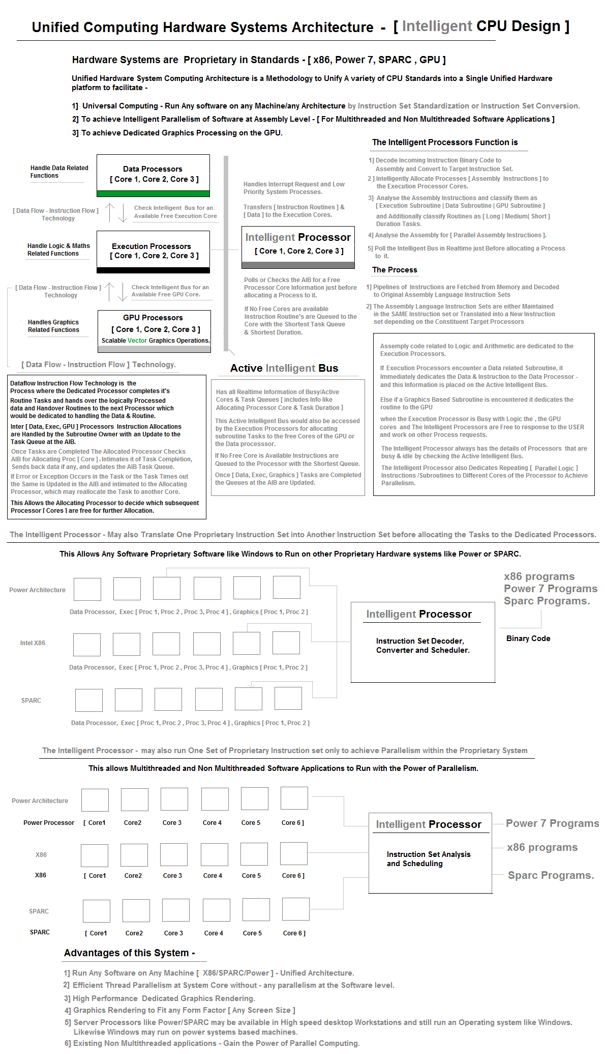
#9 Unified Computing Architecture - CPU Design ( Macro )
#10 Innovative New Technique to Create a GPS Fix from Fast Moving LEO Satellites like IRIDIUM.
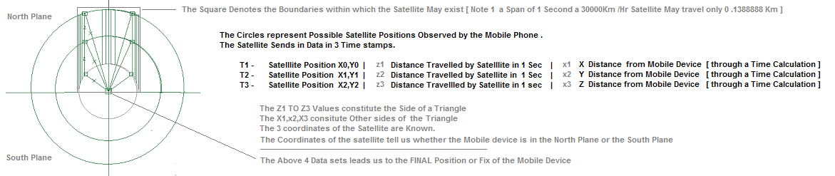
Tranditional GPS technology involves a Mobile Phone or any Device Obtining a Position fix by Getting a Signal Fix from 3-4 GPS Satellites. This technique is Perfect, however too Slow and High Energy [ Battery ] Consuming for many Applications on mobile Devices. An Alternative Position Fix has been Designed that involves an LEO satellite like Iridium. The Satellite follows a Fixed Path on the Earth [ Fixed Coordinates e.g x0,y0 - x1,y1 - x2,y2 ] and Mobile devices seek it's Location.
The STEX GPS Fix Technique Involves the Mobile device Querying a LEO Satellite for it's Position. The Mobile Devices is Returned with 3 Time stamp Values consisting of Time Stamp, Present Coordinates of the Satellite, and Distance travelled by the Satellite and Distance from the Mobile Device. The Coordinates Obtained in the 3 successive Time stamps Reveals whether the Satellite is in the North Plane or South Plane [ the North or the South of the Device ]. The [ x0,y0 ] [ x1,y1 ] [ x2,y2 ] cordinates reveal the Distance travelled by the satellite in 3 Time stamps. E.g. [ 3km, 3km, 3km in 3 seconds - This forms a X side of a Triangle ]. The Distance between the 3 Satellite Coordinates and the Mobile Device is also Available. This Completes the Data points of a Triangle and Leads us to a Position Fix.
#11 Advanced Fullfilment systems :
It is an Advanced Fullfilment Network Based on Spatial Advanced Enterprise Architecture,
Spatial Systems Engineering and Hardware cpu reflection systems. STEX has designed
this System in analogy to a Digital Freeway/ Microprocessor ( with inbuilt Primary/secondary
cache system).
#12 Solving the Information scaling Problem using Message Boards/Forums social networks, which have a large Community of Network/forum members.
Forums/Communities Include - E.g. Stackoverflow, Code project, online news papers, Skype, Linkedin, WikiPedia, Personal Blogs, Youtube, Search Engines, twitter, Google plus, Facebook, Email, Ebay.
Exclusive Technogy design strategy for Forums/Social Networks to monetize their Information systems by placing sponsorship/Ad links in every message/Article posted on the message boards or messages of social networks.( A revenue share model for Forum Owners as well as forum/Network members ). Finally Links to messages/Articles could also be posted on the STEX Grid as meta data, to scale Information search and could include ( News Articles, scholarly articles, , Resumes, Profiles, Talent Scouting Videos's, Product Showcases, creatives & Creative Stories ).
How it works ?
Sponsorer's buy Sponsorship/Ad Credits from Forums like Stack Overflow, Code Project, Search etc. Forums place sponsorship Ad Links on ther articles, search engine links and message boards. Message boards/articles have an account id & when public users click on the message board's Sponsorship links - The Forums deduct Credit from sponsorers. "Partial credits" are transferred to article owners and members's message postings ( when people click on the sponsorship links, placed at the bottom of the Message posting or Article. )

"Remaining credits" are transferred to the Forum owners as monetization fee. The credits earned by members and forum owners can be converted to currency - dollars, euro etc. Sponsorship AD link consists of [ Message Owner ID/Article owner id, sponsorer's id, url Link, Text Description ]. Sponsorer's ID can be either searched in a directory & used through the Link Assignment API, or can be at Automatically assigned to Forum Member/user posting through the Link Assignment API.
Forum users also post the same Message or Article links on the stex grid system & earn currency credits ( when sponsorship links are clicked on the stex grid search engine ). The same forum members/users also earn Currency credits, when users click on sponsorship links at the forum article/message board. ( This is a Twin strategy way to earn currency and spread information ). This technique would reduce advertising costs and sponsorer's may also carry out targeted marketing.
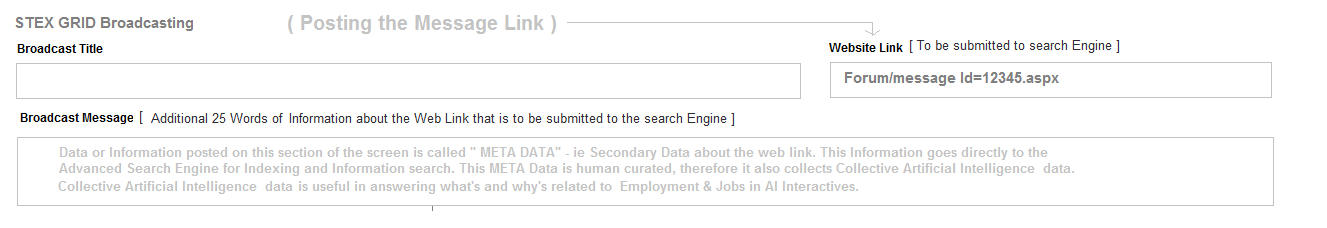
Information scaling by posting message or article links on the STEX Grid & the Forum Boards also increases probability of Link Clicks & Information flow at a low cost. This simultaneously scales the STEX Grid'S Intelligence system. Forum owners earn revenue, members earn revenue, stex grid earns revenue & sponsorer's gain Information traction. This solution was conceived by the Concept of "Mathematically Balancing Equations and variables using vectors & relations ).
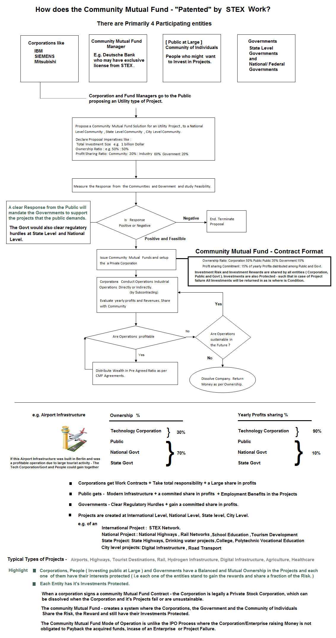
#13 Community Mutual Funds
Stock are instruments to hold partial ownership of stocks , transacted through Stock Markets. Mathematics proves that stock market trading through Stock market trading is a Zero sum problem ( GAME theory evaluation & Mathematical Induction techniques from a single player game to an n Player game. ). This implies that when one player makes money through stock gains, another loses money. Successive generation of stock owners increase liquidity in Mutual funds and stock exchanges to raise value of the stock. Stock which do not have a dividend component are not liable to pay out any cash to stock owners. An Ideal condition requires cash flows from stock owners to Enterprises and vice versa. If enterprises do not pay back to the stock owners the cash flows from the enterprise to the public stock owners is nil and the stock ownership is notional. Additionally Money in stock markets is Floating Money ( Money Floats between the stock owners holding the public float ) and never reaches the Enterprise that provides the stock ( Stock Money reaches Enterprises only during an IPO, Bond issue or Loan ).
Stocks that are traded on stock exchanges exhibit a stock value that is created by a minor amount of liquidity ( Volume ) , which is a small subset of the total number of shares held by stakeholders. This stock Value representation ( created by a small section of traders ) may be grossly inaccurate in representation of the actual value of the stock. , which actually consists of a large number of subset of owners involving ( Traders, FII's, Mutual Funds, Institutional Investors, Hni's and small stock owners ).
The stock market problem can be solved by fixing the range of Future stock dividends
during an IPO process or through an AGM ( meeting ) post IPO. E.g. Declaring 15%
to 40% dividend equivalent of "the Net Profit earned yearly". The Stock market problem
can additionaly be solved by a Buy Back note issued by enterprise quoting the value
of the stock and the Quantity of stock that can be bought back by the enterprise.
These two solutions answer the simple fundamental questions - what is the pay back
amount or cost of capital raised from the stock market IPO ?
Calculating the Cost of Capital
Why do enterprises go to the stock market instead of taking a bank loan?( It's an
instrument designed to offer risk free capital ( money ) without any payback( dividend
) commitments. Stex Suggests that a payback ( dividend ) value in the range of 15%
to 40% of the "Net Profit earned yearly", could balance the Risk free nature of
the instrument, and The rest of the 60% "net profits earned yearly", could be used
for growth of the Enterprise.)
Calculating the Value of the Stock Price
An A+ Technique can be used to arrive at value's of the stock price by including Stock Value calculation parameters like
- Premium value created by the services/Product ( Good to Have services ).
- "Essentiallity" of the services offered.( A service/Industry Solution that cannot be done without )
- Attractive or Innovative Revenue Models
- Other "Present Continuous, Future Continuous & Past participle" - Financial Parameters .
- Value of Industrial Machine Assets, Factories, Buildings etc.
- Potential Scale
- Cumulative Net Earnings/Net losses ( Net volume of money storage ) over a period of time.
- Net Money Borrowed during an IPO.
- Net Debt
- Order Books
This facilitates balanced ( Tensor equations & vector maths ) sharing of business risks and business rewards between all stakeholders of the stock. e.g [ Bank, Insurance, machinery tools companies , Individuals ] and each of them have their mutual interests protected .( Vector forces and Maths relations ) The stock market Financial problem can be solved by a more systematic and Risk free Instrument called the Insured loan product( described in section #15 ) & community mutual Fund ( described in section #8 below )
Stablilizing the Stock Market by mitigating market risks of stocks.
Stocks are highly Liquid Assets, which implies stock = Cash.
if STOCK Equal to Cash, Stocks could earn Fixed deposit styled interest and Saving account styled interest from Banks, Industrial Enterprise and Financial services Industry. This stabilizes the stock price and opens three modes for earning income. This process design has advantages over the floating money principle of the stock market, where stock money, never reaches The Industrial Enterprise's account books.
- Dividends from stocks
- Interest yield on stocks by Banks or Industrial Enterprises. ( e.g a Stock price at 1500$ could earn "Interest yield" on a stock, at a value of 1200$ ).
- Price Escalation of stocks by Market Forces.
- A Stable Financial Instrument Implies Higher Participation in the Stock Market and Inturn Higher Liquidity and stability of Stock Prices.
#14 Insured Loans Instruments - Finance Loans with Integrated Insurance :
Stex has invented a new Financial Technique/Tool/Instrument called Insured Loans,
to facilitate Colateral free Technology Projects/Machinery tools projects and other
projects . ( using tensor maths and freescales ) . It is an Integrated Financial
Loan endorsed with an Integrated Risk Policy ( Insurance endorsement to cover loan
repayment failure risks ).
E.g. A loan of 25000$ Towards a Machinery project/ Tool project/ Technology project
may consitute of
- 22500$ as a Principal loan amount to be disbursed to the loanee.
- 2500$ as Insurance Risk to cover the Loan Risks, payable by the Insurer.
- The Loan can be disbursed for Technology projects, machine works projects, machine tooling projects and many other projects.
- The Loanee is obligated to return the following
- Project failure scenario/loan default scenario: Tools/Machinery ( Depreciated Assets - which can be refurbished and Resold by the machine manufacturer ) & a principal amount of 10000$ ( 10000$ or 9000$ or 8000$ or 7000$ Freescale maths ) out of the 22500$ ( Loan amount) , on Project/Busines failure
- Project success scenario/ Non loan default scenario - ( 25000$ Principal + Interest )
- Used Machines/Tools can be refurbished and marketed to People for projects.
- The Loan amount can be as high as 500k$ to 1 Million $.
- These loans are disbursed by Financial institutions in assosciation with machine tool manufacturers or by machine tool manufactureres as the sole authority. The Loans amounts depend on Type of Projects and Project machinery required. E.g. The Loan amount may be fixed for a Specific Market segment of Engineering tools - 25k$ for a Wood cutting machine type B.
- All stake holder mutual interests( Tensors - Vectors forces & Relationships ) are balanced between the loanee, Insurance company, Technology machine maker, Individuals.
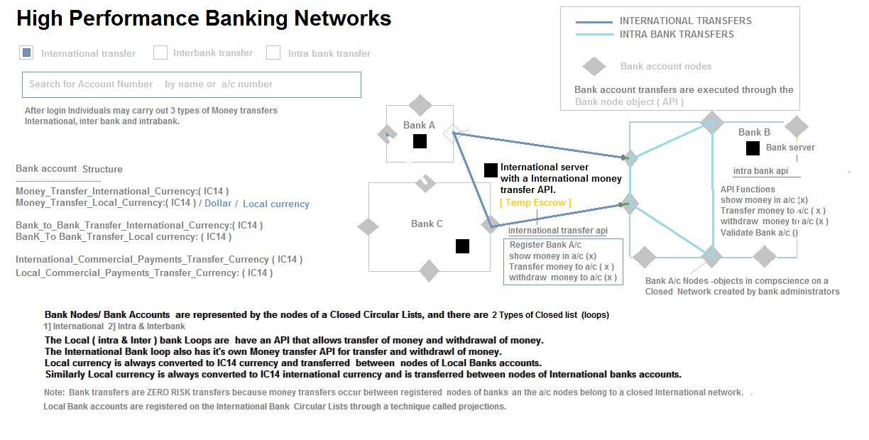
#15: Single world International Currency Paradigm
All Local currencies like ( dollars, euro, rupee ) are converted to a Single international Currency ( IC14 - International currency ) and can be reconverted back to Local Currency.
- This systems fixes the rates of the international trade currency IC14 to 200+ Local currencies of the world by Gathering Total volume of Money printed by the central banks ( of each and every country on the planet ).
- This currency fixed rates change periodically every 3 months, 6 months or a year by collecting the Volume of money printed by each Country's Central Bank.
- All Banks may be equipped to a add a single new currency column to their Databases called IC14 Currency, with a function allowing convertion of Local Currency to IC14 and vice versa
- Since IC14 is a Trade currency, all International & Local Commercial activites may be conducted in IC14 =( X Local Currency ) format
- IC14 is non devaluable and, people and enterprises, may store their assets in IC14 with no currency risks and further could use IC14 as a Trade currency.( Note Central banks buy back local currency to allow conversions of local currency like dollar to IC14 .)
- Excess money printing by any country does not devalue the currency and further does not affect Other countries economics. Local currency volumes ( liquidity can be controlled by restricing a percentage of conversion of dollar or local currency to IC14 ).e.g Allowing max 70% of dollar saving to be converted and saved as IC14.
- Expensive Derivatives based Options hedging can be avoided to mitigate currency fluctuation risks. Note: Currency fluctuation happen between each economic currency in permutations ie - eg. dollar rupee, rupee dollar, dollar yen, yen dollar, dollar euro, euro dollar . Therefore Currency Fluctuations between a large Number of Permutations ( 200+ countries * 200+ countries/2 ) can be avoided.e.g. US trades with china ( dollar yuan ), , US trades with india ( dollar rupee ), us trades with Australia ( dollar Aus dollar ).
- Note: Currency markets are controlled only a few Entities/Traders are do not actually reflect the real exchange rates.
- Illegal Currency CASH Flows between entities in International trade can be traced easily.
- No Printing of Cash/Notes is required to use this currency.
- Regulatory central banks can easy trace Capital Account Convertbility numbers by monitoring - IC14 conversions to local currency and vice versa through banks
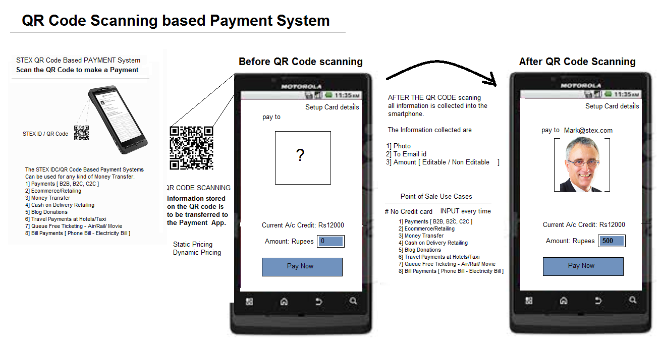
#16 QR Payment technology/QR Code Based Payment System
A novel new payment method that facilitates payments on the web and real world,
through QR Codes. It works by a smart phone scanning a QR Code and facilitating
a "High Speed Secured Financial Transaction". The QR Code that is scanned could
be a QR Code that resides on a:
- Computer/web screen
- News Paper Ad
- A Business card
- A Printed Paper Bill
- An E-commerce Cart
The following is a QR Code-based payment system diagram - as it appears on a smartphone app. The QR Code contains all vital elements necessary for a financial transaction..
-
1: No filling web forms with credit card details to make payments on websites.
2: can be used to transfer cash on delivery.
3: The system introduces the concept of the one world integrated single "International currency", where people convert their local currency to an International currency to carry out trade and reconvert it back to local currencies when required.
4: Currency Risk are Mitigated by a Non Fluctuating Currency system.
5: Credit card risks are reduced from Billion of dollars to near Zero.
6: payments on the web involve 3- 4 Hops on servers. This system reduces payment system hops to 1 server Transaction.
#17 Queue Free Ticketing Systems :
Most ticketing or ticket booking systems in the market are Queue Based Ticketing systems. STEX has designed a Queue Free Ticketing system using QR COdes.
#18 High Performance banking Networks :
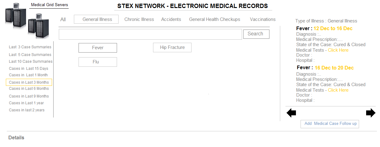
#20 Electronic Medical Records
The Electronic Medical Record Technology Services - Is a Planet Scale Fluid Transactional
Electronic Health Record System for Individuals worldwide. The System Maintains
Highly Secure & Private Medical Health Records For All Individuals, Accessible
to Any Medical Doctor or Health Center. The System has Entire set of Health Records
from Birth to Death, and can be Updated by Doctors at absolutely any Location.
Since The System Collects Medical diagnostics Information of a large number of Patients,
endorsed by Multiple Doctors or Medical Practioners, the Data is Statistically &
Collectively Intelligent. This Intelligent Data aids doctors by Providing them Artificial
Medical Intelligence - i.e Providing them Proactive "Dignosis & Prescription"
Information about Similar Successful Medical Cases Recorded by the EMR System, on
Multiple Patients worldwide, Prescribed or Endorsed by Doctors Worldwide.
Since Electronic Medical Records is not a High Frequency - High Activity System
- It scales very Easily with a Reasonably Large Datastore.
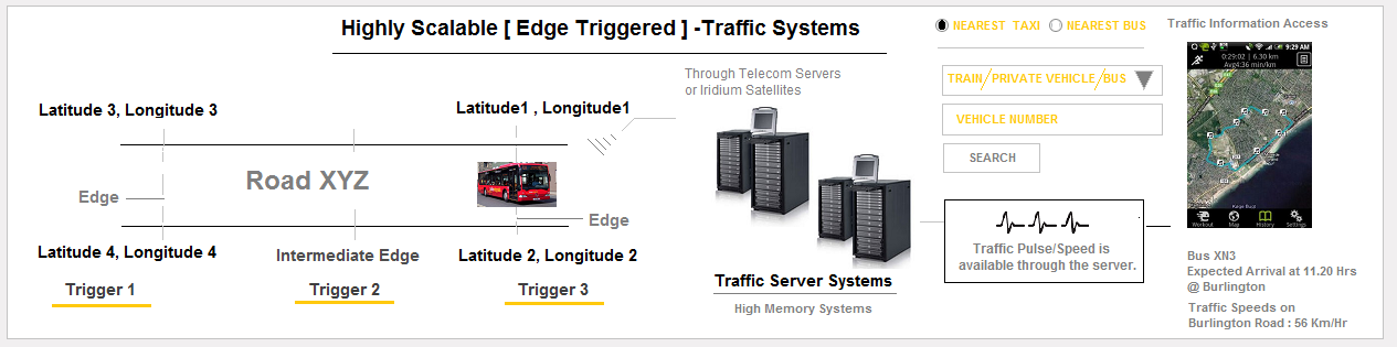
#21 Air/Marine/Road - Navigation & Traffic Systems
Traditionally Engineered Traffic Systems are sometimes a difficult proposition because
traditional technology includes camera based/Laser based solutions [ which may be
very accurate, but do not scale well. It is because fixing a camera's on every street
or road is a difficult process ]. STEX traffic Systems include 3G/4G/ Wi-Fi enabled
devices that are placed inside public transport and cars, that trigger Intelligent
traffic Information through 3G/4G/4G Internet Networks to High Speed Memory
Machines. Apart from Traffic Information Triggering, the devices also allow Internet
access [ Wifi Hotspot ] in Cars and Public Transport systems. These Devices are also
useful in notifying Emergency situations.
Position and Speed Information [ Telemetry Data ] in a Traffic Zone, is Broadcast
or Communicated by the Vehicle at the 3 Zones of the road - [ Entry/Exit and Intermediate
Zones ].
Arrays of Data Points representing each zone, can be used to Store a set Latitude Longitude
Datapoints that Consitutes a Road. These Datapoints may be used to Provide Accurate "Any Point
to Any Point" - Map based Navigation. This information may also be used to provide
alternate Traffic Routes through this live traffic system.
[ Note: Zonal Data Points can be collected by Driving a Car through a Particular Road
] And Marking 3 LAT LONG points per road. The Entire Traffic System and WayFinding System
would be available through Artificial Intelligence Interactive Programs.
A Very Important Advantage of this System is that, A low Vehicle count ( with the
Device installed ), is sufficient to generate traffic information in a TRAFFIC zone.
10 in 50/100 Vehicles may be able to Generate a Traffic Pulse/Traffic Speed information.
Systems like Road Traffic Systems, Operate purely in only In Memory Server Systems
, and transfer Records to Database only under certain exceptional Conditions, like Accidents
or incidents.
#22 Logistics
A similar Logistics Technology Systems provides - Vital real time [ Capacity and
Cost Information ] through the Digital systems, Connecting Transporters, Freight
Forwarders and Consignees. The System Caters to Transportation systems like
- Shipping
- Air
- Rail
- Road
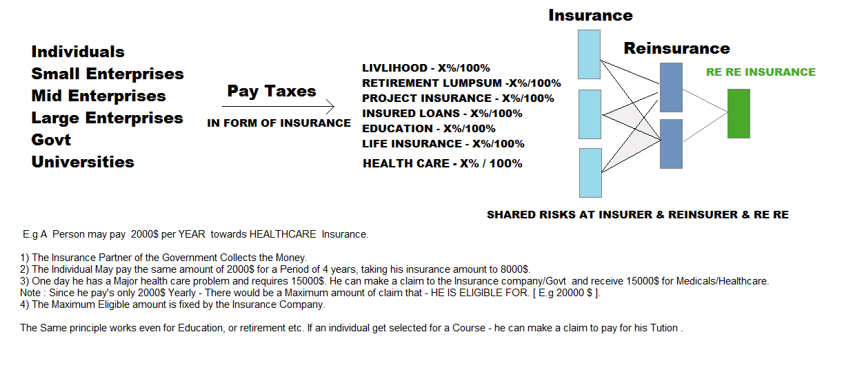
#23 Insurance TAX Reforms Project.
20% Workforce/Industry Taxes go towards Insurance & 15% Workforce/Business tax go
towards govt taxes. Insurance TAX is collected in the
following categories. ( Advanced Taxation Filing Format )
- LIVLIHOOD INSURANCE - X%/100%
- RETIREMENT LUMPSUM INSURANCE - X%/100%
- PROJECT INSURANCE - X%/100%
- INSURED LOANS INSURANCE - X%/100%
- EDUCATION INSURANCE- X%/100%
- LIFE INSURANCE - X%/100%
Insurance Firms Insure The Workforce/Industry Insurance corpus at RE Insurance
firms. ( E.g Swiss Re ) to mitigate/Share risks. Insurance firms may be PPP Styled
( A Partnership between Private and Public ).
Reinsurer's could also mitigate or share risks by going to [ Re Re ] Insurer Which is a
"Reinsurance firm" for Insurer's and Reinsurers.
A certain portion of The insurer's corpus and reinsurer's corpus (E.G. 2%-3%) goes to the
[ RE RE Insurance companies ] which insures insurance & Re insurance companies.
RE RE Companies could be a division within the Reinsurer like MUNICH RE/SWISS RE.
Note: Different countries Insurer's pay different premiums to reinsurer's based on their respective
Risk Profiles. Reinsurance players collect data & insurance premium from Insurer's via insurance companies
( which collect Insurance Tax).
The Scheme works in such that all entities - Individuals, Enterprises and Universities and govts pay taxes
towards insurance so as to benefit from Insurance Claims ( Incase they Incur Risk or Losses or loss of Livlihood etc.)
This allows Govts to collect money from Workforce and Industries for appropriate use.
The Higher the insurance an individual or enterprise pays, the higher is the proportional return in case of a claim,
which is called a prorata Insurance. This instigates all Types of Entities to Contribute to Insurance Taxes,
which gives them "Insurance protection" in the above categories.
2 Insurance and Reinsurance - Philosophies exist from the corpus point of View -
- INSURANCE COMPANIES BUILD CORPUS AND DONT INVEST to grow the corpus
- INSURANCE COMPANIES INVEST IN PROJECTS to grow the corpus.
Insurance Tax is linked to your bank account and every time
there is a claim bank acccounts are checked to ascertain livlihood loss/Retirement or to transfer
Insurance claim amounts.
#20 Electronic Medical Records
The Electronic Medical Record Technology Services - Is a Planet Scale Fluid Transactional Electronic Health Record System for Individuals worldwide. The System Maintains Highly Secure & Private Medical Health Records For All Individuals, Accessible to Any Medical Doctor or Health Center. The System has Entire set of Health Records from Birth to Death, and can be Updated by Doctors at absolutely any Location.
Since The System Collects Medical diagnostics Information of a large number of Patients, endorsed by Multiple Doctors or Medical Practioners, the Data is Statistically & Collectively Intelligent. This Intelligent Data aids doctors by Providing them Artificial Medical Intelligence - i.e Providing them Proactive "Dignosis & Prescription" Information about Similar Successful Medical Cases Recorded by the EMR System, on Multiple Patients worldwide, Prescribed or Endorsed by Doctors Worldwide.
Since Electronic Medical Records is not a High Frequency - High Activity System - It scales very Easily with a Reasonably Large Datastore.
#21 Air/Marine/Road - Navigation & Traffic Systems
Traditionally Engineered Traffic Systems are sometimes a difficult proposition because traditional technology includes camera based/Laser based solutions [ which may be very accurate, but do not scale well. It is because fixing a camera's on every street or road is a difficult process ]. STEX traffic Systems include 3G/4G/ Wi-Fi enabled devices that are placed inside public transport and cars, that trigger Intelligent traffic Information through 3G/4G/4G Internet Networks to High Speed Memory Machines. Apart from Traffic Information Triggering, the devices also allow Internet access [ Wifi Hotspot ] in Cars and Public Transport systems. These Devices are also useful in notifying Emergency situations.
Position and Speed Information [ Telemetry Data ] in a Traffic Zone, is Broadcast or Communicated by the Vehicle at the 3 Zones of the road - [ Entry/Exit and Intermediate Zones ]. Arrays of Data Points representing each zone, can be used to Store a set Latitude Longitude Datapoints that Consitutes a Road. These Datapoints may be used to Provide Accurate "Any Point to Any Point" - Map based Navigation. This information may also be used to provide alternate Traffic Routes through this live traffic system.
[ Note: Zonal Data Points can be collected by Driving a Car through a Particular Road ] And Marking 3 LAT LONG points per road. The Entire Traffic System and WayFinding System would be available through Artificial Intelligence Interactive Programs.
A Very Important Advantage of this System is that, A low Vehicle count ( with the Device installed ), is sufficient to generate traffic information in a TRAFFIC zone. 10 in 50/100 Vehicles may be able to Generate a Traffic Pulse/Traffic Speed information.
Systems like Road Traffic Systems, Operate purely in only In Memory Server Systems , and transfer Records to Database only under certain exceptional Conditions, like Accidents or incidents.
#22 Logistics
A similar Logistics Technology Systems provides - Vital real time [ Capacity and Cost Information ] through the Digital systems, Connecting Transporters, Freight Forwarders and Consignees. The System Caters to Transportation systems like
- Shipping
- Air
- Rail
- Road
#23 Insurance TAX Reforms Project.
20% Workforce/Industry Taxes go towards Insurance & 15% Workforce/Business tax go towards govt taxes. Insurance TAX is collected in the following categories. ( Advanced Taxation Filing Format )
- LIVLIHOOD INSURANCE - X%/100%
- RETIREMENT LUMPSUM INSURANCE - X%/100%
- PROJECT INSURANCE - X%/100%
- INSURED LOANS INSURANCE - X%/100%
- EDUCATION INSURANCE- X%/100%
- LIFE INSURANCE - X%/100%
Insurance Firms Insure The Workforce/Industry Insurance corpus at RE Insurance firms. ( E.g Swiss Re ) to mitigate/Share risks. Insurance firms may be PPP Styled ( A Partnership between Private and Public ). Reinsurer's could also mitigate or share risks by going to [ Re Re ] Insurer Which is a "Reinsurance firm" for Insurer's and Reinsurers.
A certain portion of The insurer's corpus and reinsurer's corpus (E.G. 2%-3%) goes to the [ RE RE Insurance companies ] which insures insurance & Re insurance companies. RE RE Companies could be a division within the Reinsurer like MUNICH RE/SWISS RE.
Note: Different countries Insurer's pay different premiums to reinsurer's based on their respective Risk Profiles. Reinsurance players collect data & insurance premium from Insurer's via insurance companies ( which collect Insurance Tax). The Scheme works in such that all entities - Individuals, Enterprises and Universities and govts pay taxes towards insurance so as to benefit from Insurance Claims ( Incase they Incur Risk or Losses or loss of Livlihood etc.) This allows Govts to collect money from Workforce and Industries for appropriate use. The Higher the insurance an individual or enterprise pays, the higher is the proportional return in case of a claim, which is called a prorata Insurance. This instigates all Types of Entities to Contribute to Insurance Taxes, which gives them "Insurance protection" in the above categories.
2 Insurance and Reinsurance - Philosophies exist from the corpus point of View -
- INSURANCE COMPANIES BUILD CORPUS AND DONT INVEST to grow the corpus
- INSURANCE COMPANIES INVEST IN PROJECTS to grow the corpus.
Quote from Film Die Hard 4 - "I'm doing the Country a favour... But the question is, is the Country willing to pay for it?"